
NCERT Exemplar Class 10 Science Chapter 12 Electricity Solutions
NCERT Exemplar Solutions for Class 10 Science Chapter 12 Electricity covers all the important questions and answers as well as advanced level questions. It helps in learning about the electric current, charge, conductors, insulators, electrons, convection, potential difference, ohms law, resistors and resistance.
The NCERT Exemplar solutions for class 10 science is very important for board exams. NCERT Exemplar Solutions for Class 10 Science Chapter 12 Electricity is provided by our experts. They prepared the best solutions which help the students in understanding the solutions in an easy way. This chapters also covers the other topics like electric fuse, short circuit, overloading, factors on which resistance of a conductor depends and safety devices.

Chapter Name | Chapter 12 Electricity |
Book Title | NCERT Exemplar for Class 10 Science |
Related Study |
|
Topics Covered |
|
NCERT Exemplar Solutions for Chapter 12 Electricity Class 10 Science
Multiple Choice Questions
1. A cell, a resistor, a key and ammeter are arranged as shown in the circuit diagrams of Figure12.1. The current recorded in the ammeter will be

(a) maximum in (i)
(b) maximum in (ii)
(c) maximum in (iii)
(d) the same in all the cases
Solution
(d) the same in all the cases
The current will be same in all the circuits as there are no changes in any of the circuits.
2. In the following circuits (Figure 12.2), heat produced in the resistor or combination of resistors connected to a 12 V battery will be

(a) same in all the cases
(b) minimum in case (i)
(c) maximum in case (ii)
(d) maximum in case (iii)
Solution
(c) maximum in case (ii)
The two resistors are connected in series. The total resistance will be less than individual resistances in figure (iii) as they are connected parallel. Higher resistance produces more heat.
3. Electrical resistivity of a given metallic wire depends upon
(a) its length
(b) its thickness
(c) its shape
(d) nature of the material
Solution
(d) nature of the material
4. A current of 1 A is drawn by a filament of an electric bulb. Number of electrons passing through a cross section of the filament in 16 seconds would be roughly
(a) 1020
(b) 1016
(c) 1018
(d) 1023
Solution
(a) 1020

The number of electrons flowing is 1020 electrons
5. Identify the circuit (Figure 12.3) in which the electrical components have been properly connected.

(b) (ii)
(c) (iii)
(d) (iv)
(b) (ii)
(a) 1/5 Ω
(b) 10 Ω
(c) 5 Ω
(d) 1 Ω
(d) 1 Ω

(a) 1/5 Ω
(b) 1/25 Ω
(c) 1/10 Ω
(d) 25 Ω
(b) 1/25 Ω
1/R = 5 + 5 +5+ 5 + 5 = 25 Ω

(c) (iii)
(d) (iv)
(a) (i)
9. Which of the following represents voltage ?
(a) Work done/(Current × Time)
(b) Work done × Charge
(c) (Work done × Time)/Current
(d) Work done × Charge × Time
Solution
(a) Work done/(Current × Time)
10. A cylindrical conductor of length l and uniform area of crossnsection A has resistance R. Another conductor of length 2l and resistance R of the same material has area of cross section
(a) A/2
(b) 3A/2
(c) 2A
(d) 3A
Solution
(c) 2A
⇒ A = 2A
11. A student carries out an experiment and plots the V-I graph of three samples of nichrome wire with resistances R1 , R2 and R3 respectively (Figure.12.5). Which of the following is true?

(a) R1 = R2 = R3
(b) R1 > R2 > R3
(c) R3 > R2 > R1
(d) R2 > R3 > R1
Solution
(c) R3 > R2 > R1
Current flow is inversely proportional to resistance. Highest resistance will show least amount of current.
12. If the current I through a resistor is increased by 100% (assume that temperature remains unchanged), the increase in power dissipated will be
(a) 100 %
(b) 200 %
(c) 300 %
(d) 400 %
Solution
(c) 300 %
Heat generated is directly proportional to square of current. Therefore, when current doubles, the dissipation of heat will multiply by 4.
13. The resistivity does not change if
(a) the material is changed
(b) the temperature is changed
(c) the shape of the resistor is changed
(d) both material and temperature are changed
Solution
(c) the shape of the resistor is changed
14. In an electrical circuit three incandescent bulbs A, B and C of rating 40 W, 60 W and 100 W respectively are connected in parallel to an electric source. Which of the following is likely to happen regarding their brightness?
(a) Brightness of all the bulbs will be the same
(b) Brightness of bulb A will be the maximum
(c) Brightness of bulb B will be more than that of A
(d) Brightness of bulb C will be less than that of B
Solution
(c) Brightness of bulb B will be more than that of A
As the three bulbs are connected in parallel, so the resistance of the combination would be less than arithmetic sum of individual resistances of all the bulbs. Therefore, there will be no negative effect on current flow. As a result, the bulbs will glow according to their wattage.
15. In an electrical circuit two resistors of 2 Ω and 4 Ω respectively are connected in series to a 6 V battery. The heat dissipated by the 4 Ω resistor in 5 s will be
(a) 5 J
(b) 10 J
(c) 20 J
(d) 30 J
Solution
(c) 20 J
Equivalent resistance of the circuit is R = 4+2 = 6Ω

16. An electric kettle consumes 1 kW of electric power when operated at 220 V. A fuse wire of what rating must be used for it?
(a) 1 A
(b) 2 A
(c) 4 A
(d) 5 A
Solution
(d) 5 A
P=V ×I
Or, 1000 W= 220 V×I

17. Two resistors of resistance 2 Ω and 4 Ω when connected to a battery will have
(a) same current flowing through them when connected in parallel
(b) same current flowing through them when connected in series
(c) same potential difference across them when connected in series
(d) different p
Solution
(b) same current flowing through them when connected in series
In series combination the resistors receive a common current as the current does not get divided into branches.
18. Unit of electric power may also be expressed as
(a) volt ampere
(b) kilowatt hour
(c) watt second
(d) joule second
Solution
(b) kilowatt hour
Volt-ampere(VA) is the unit for apparent power. Watt second(also watt-second, symbol W s or W.s) is a derived unit of energy and is equivalent to the joule. The joule-second is the unit used for Planck’s constant.
Short Answer Questions
19. A child has drawn the electric circuit to study Ohm’s law as shown in Figure 12.6. His teacher told that the circuit diagram needs correction. Study the circuit diagram and redraw it after making all corrections.


Current P = I2R
⇒ 18W = I2 × 2Ω
⇒ I2 = 18W/2Ω = 9
⇒ I = 3A
This is the maximum current that can flow through the three resistors.
21. Should the resistance of an ammeter be low or high? Give reason.
Solution
The resistance of an ammeter should be close to zero. Ideally it should be zero ohm. If the resistance of the ammeter is non-zero then the true current will be affected substantially.
22. Draw a circuit diagram of an electric circuit containing a cell, a key, an ammeter, a resistor of 2 Ω in series with a combination of two resistors (4 Ω each) in parallel and a voltmeter across the parallel combination. Will the potential difference across the 2 Ω resistor be the same as that across the parallel combination of 4Ω resistors? Give reason.
Solution

⇒ R = 2Ω
The resistance of the fuse wire is greater than that of the main wiring. The fuse wire melts and breaks the circuit when there is significant increase in the electric current.. This prevents the damage of electrical appliance.
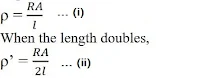
Resistivity is the property of the conductor through which it resists the flow of electric current. Resistivity for any particular material is unique. Resistance is directly proportional to length of conductor and inversely proportional to current flow. As the length is doubled, the resistance also doubles but current flow reduces to half. This is the reason why the ammeter reading decreases.
25. What is the commercial unit of electrical energy? Represent it in terms of joules.
Solution
Commercial unit of electrical energy is killowatt-hour
1 kw/hr = 1 kW h
= 1000 W × 60 × 60s
= 3.6 × 10⁶ J
26. A current of 1 ampere flows in a series circuit containing an electric lamp and a conductor of 5 Ω when connected to a 10 V battery. Calculate the resistance of the electric lamp. Now if a resistance of 10 Ω is connected in parallel with this series combination, what change (if any) in current flowing through 5 Ω conductor and potential difference across the lamp will take place? Give reason.
Solution

In series total resistance = 5 + R

Now, potential drop across lamp + conductor = 10 V
Therefore, V across the lamp = I × R = 1 × 5 = 5 Volt
27. Why is parallel arrangement used in domestic wiring?
Solution
In domestic wiring, parallel arrangement is used as it provides the same potential difference across each electrical appliance.
28. B1 , B2 and B3 are three identical bulbs connected as shown in Figure 12.8. When all the three bulbs glow, a current of 3A is recorded by the ammeter A.
(i) What happens to the glow of the other two bulbs when the bulb B1 gets fused?
(ii) What happens to the reading of A1 , A2 , A3 and A when the bulb B2 gets fused?
(iii) How much power is dissipated in the circuit when all the three bulbs glow together?
Solution
(i) In parallel circuit, the potential difference does not get divided. Therefore, if one bulb is fused, then the glowing of other bulbs will not be affected.
(ii) Ammeter A shows a reading of 3A. This means each of the Al, A2, and A3 show 1 A reading.
Now, P= I2R
= (3A)2× 1.5 Ω
= 13.5 W

Long Answer Questions
29. Three incandescent bulbs of 100 W each are connected in series in an electric circuit. In another circuit another set of three bulbs of the same wattage are connected in parallel to the same source.
(a) Will the bulb in the two circuits glow with the same brightness? Justify your answer.
(b) Now let one bulb in both the circuits get fused. Will the rest of the bulbs continue to glow in each circuit? Give reason.
Solution
(a) In series connection, the resistance of the bulbs will be three times the resistance of single bulb. Therefore, the current in the series combination will be one-third of the current in each bulb in parallel combination. This in parallel combination the bulbs will glow more brightly.
(b) In series combination, the bulbs will stop glowing as the circuit is broken and therefore the current is zero. However, in parallel connection the bulbs will continue to glow with the same brightness.
30. State Ohm’s law? How can it be verified experimentally? Does it hold good under all conditions? Comment.
Solution
Ohm’s law states that at constant temperature, the potential difference (voltage) across an ideal conductor is proportional to the current through it.
V/I = R

- Set up a circuit as shown in figure. The circuit consists of a nichrome wire XY of length, say 0.5 m, an ammeter, a voltmeter and four cells of 1.5 V each.
- First use only one cell as the source in the circuit and note the reading in the ammeter I, for the current and reading of the voltmeter V for the potential difference across the nichrome wire XY in the circuit. Tabulate them in the Table given
- Next connect two cells in the circuit and again note down the respective readings of the ammeter and voltmeter.
- Repeat the above steps using three cells and then four cells in the circuit separately.

31. What is electrical resistivity of a material? What is its unit? Describe an experiment to study the factors on which the resistance of conducting wire depends.
Solution
The inherent property of a conductor by virtue of which it resists the flow of electric current is known as resistivity. Resistivity of each material is unique.
The SI unit of resistivity is Ω m.
Experiment to study the factors on which the resistance of conducting wire depends:
Set up:
- Take a nichrome wire, a torch bulb, a 10 W bulb and an ammeter (0 –5 A range), a plug key and some connecting wires.
- Connect four dry cells of 1.5 V each in series with the ammeter leaving a gap XY in the circuit, as shown in Fig. 12.4.
- Complete the circuit by connecting the nichrome wire in the gap XY. Plug the key. Note down the ammeter reading. •Now, change the length of the nichrome wire and take the ammeter reading.
- Next, change the thickness of nichrome wire and note down the ammeter reading.
- After few steps, use copper wire for the experiment. Attach copper wire and note down the ammeter reading.
- One by one change the length and thickness of the copper wire and observe the ammeter reading.
- Repeat the steps with different materials.
Observation:
It is observed that the resistance depends on:
- Material of conductor.
- Length of conductor.
- Area of cross section.

32. How will you infer with the help of an experiment that the same current flows through every part of the circuit containing three resistances in series connected to a battery?
Solution
- Connect the three resistors R1, R2, R3 in series to make the circuit.
- Use ammeter to see the current flowing through the three resistors.
- Remove R1 and take the reading of potential difference of R2 and R3
- Remove R2 and take the reading of potential difference of R1 and R3

Ammeter reading is same in each case. This shows same current flows across each resistors connected in series.
33. How will you conclude that the same potential difference (voltage) exists across three resistors connected in a parallel arrangement to a battery?
- Take three resistors RI. ity. and R3 and connect them in parallel to make a circuit as shown in figure.
- Use voltmeter to take reading of potential difference of three resistors in parallel combination.
- Now, remove the resistor R1 and take the reacting of potential difference of remaining resistors combination.
- Then, remove the resistor R, and take the reading of potential difference of remaining resistor.

Observation:
It is observed that in each case the voltmeter reading is the same. This shows that in parallel arrangement, same potential difference exists across each resistor.
34. What is Joule’s heating effect? How can it be demonstrated experimentally? List its four applications in daily life.
Solution
According to Joules heating effect, the heat produced in a resistor is:
- Directly proportional to square of current.
- Directly proportional to resistance.
- Directly proportional to the time of current flowing through the resistor.
H = I2 Rt
H is heating effect,
I is electric current,
R is resistance and
t is time
Experiment to demonstrate Joules law of heating
- Take an immersion rod and connect it to a socket which in turn is connected to a regulator.
- It is important as the regulator controls the amount of current flowing through a device.
- Keeping the pointer of regulator at minimum reading, measure the time taken by immersion rod to heat a certain amount of water.
- Next, increase the pointer of regulator to the next level.
- Measure the time taken by immersion rod to heat the same amount of water.
- Repeat above step for higher levels on regulator to measure the time.
35. Find out the following in the electric circuit given in Figure 12.9

(b) Current flowing through 4 Ω resistor
(c) Potential difference across 4 Ω resistance
(d) Power dissipated in 4 Ω resistor
(e) Difference in ammeter readings, if any
Solution
(a) Since, two 8 Ω resistors are in parallel, then their effective resistance Rρ is given by
1/ Rρ = 1/R1 + 1/R2 = 1/8 + 1/8 = 1/4
= Rρ = 4 Ω
(b) Total resistance in the circuit
R = 4 Ω + Rρ = 4 Ω + 4 Ω = 8 Ω
Current through the circuit,
I = V/R = 8/8 = 1A
Thus, current through 4 Ω resistor is 1 A as 4 Ω and Rρ are in series and same current flows through them.
(c) Potential difference across 4 Ω resistor is potential drop by the 4 Ω resistor.
i.e. V = IR = 1 × 4 = 4V
(d) Power dissipated in 4 Ω resistor
P = I2R = I2 × 4 = 4
(e) There is no difference in the reading of ammeters A1 and A2 as same current flows through all elements in a series current.


0 Comments
Comment Related Post
Emoji